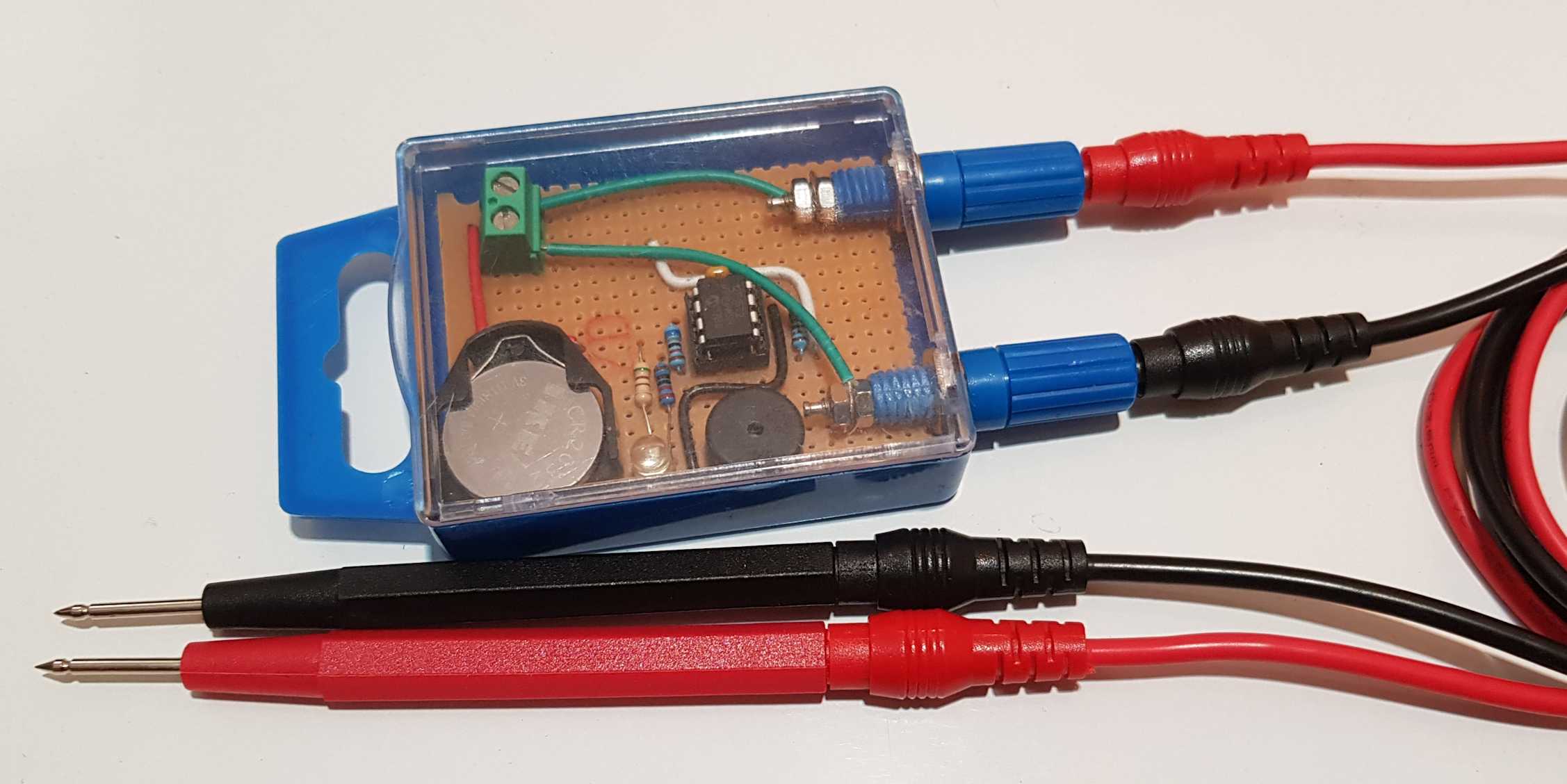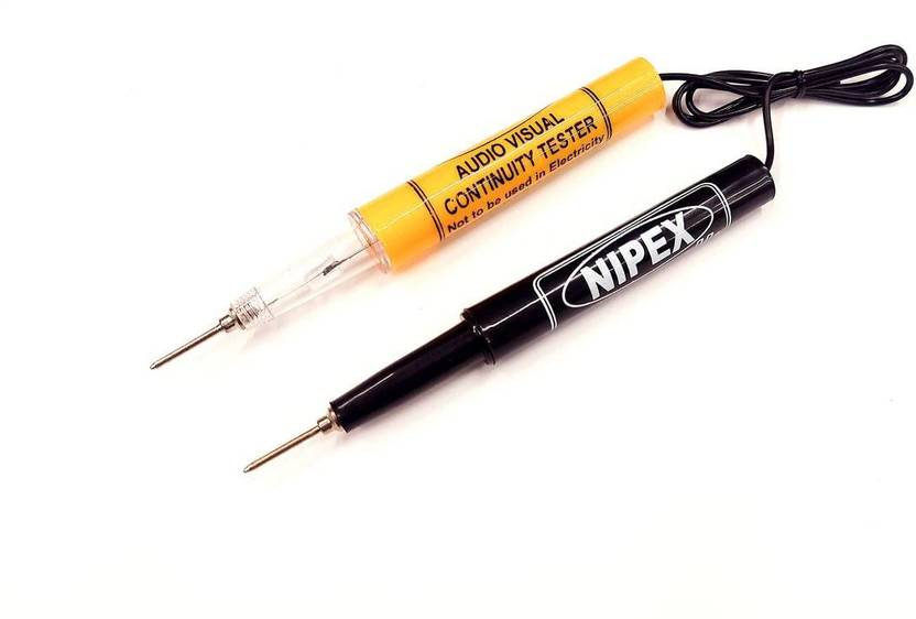
How To Make A Continuity Tester Circuit vrogue.co - A buzzer plays very important part in a continuity tester because you can identify a connection while looking in the faulted circuit by hearing the buzzer sound and you don't have to look at the continuity tester frequently. This continuity tester with buzzer works on live circuits. Here the circuit for a simple audible continuity tester with a buzzer. It. You should also read this: Test Achievement Please Ignore

Simple Continuity Tester With Buzzer Electronic circuit projects - A continuity tester is a simple device consisting of two testing probes and a light (led) or buzzer indicator. Create continuity tester circuit with buzzer and led for check solder joint defects, not kill components on pcb, as probe gives tiny current and voltage. Detachable remote indicator can be used to trace multiple cable runs In addition, a clear buzzer. You should also read this: Blow Door Test

simple continuity tester using buzzer YouTube - Very important, as common continuity testers are used with the power source disconnected. Supplied with martindale tl49 test leads The loud 85db buzzer makes it ideal for use in noisy environments. The ct20 continuity tester features a bright flashing led and loud pulsating beeper to indicate local continuity making it ideal for use in environments where excessive noise is present.. You should also read this: Can I Do A Paternity Test While Pregnant

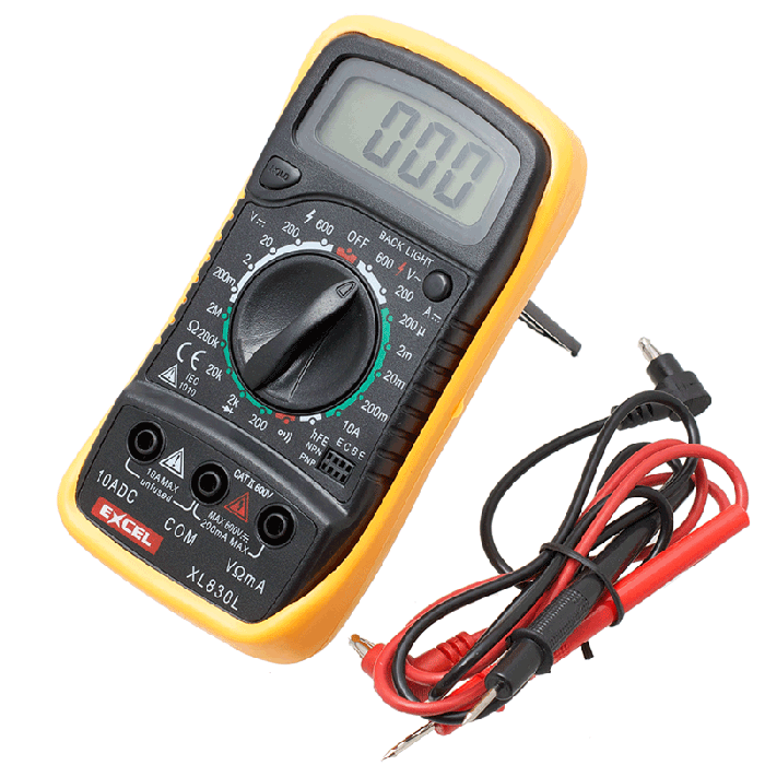
Tandy Digital Multimeter with Continuity Buzzer - Detachable remote indicator can be used to trace multiple cable runs In addition, a clear buzzer sound confirms the presence of a complete circuit, making it ideal for use in noisy environments. A buzzer plays very important part in a continuity tester because you can identify a connection while looking in the faulted circuit by hearing the buzzer sound and. You should also read this: Free Capa Practice Test

Continuity Tester With Buzzer Circuit Diagram Continuity Tes - The voltage at the inverting terminal (pin2) has adjusted with a potentiometer. Detachable remote indicator can be used to trace multiple cable runs The indicator is usually a light or, more commonly, a buzzer. If you are looking for a simple circuit to test continuity of wires and long conductors, the explained 7 easy to build continuity circuits are the. You should also read this: Fe Vs Fi Test
JOYOLEDER Spannungsprüfer Kfz Stromkreistester,624V Power Short - Fluke’s continuity test is astonishingly good at overcoming poor probes, but on other meters, good probes are critical. It checks the connection and lets us know if the connection or wire on the pcb is broken or the circuit is open due to failed components. Very important, as common continuity testers are used with the power source disconnected. Fluke’s multimeters. You should also read this: Wise Test Virginia

How To Make A Continuity Tester With Buzzer Rechargeable Continuity - The very best in this regard, of all i’ve tried, are probe master probes, whose sharp points and gold plating dramatically improve the continuity testing on most meters. Fluke’s multimeters are renowned for having the best continuity checkers, being both fast and latching. A continuity tester is a device that checks and identifies a connection between two points. The indicator. You should also read this: Yale Brown Obsessive Compulsive Scale Test

ERH India 1Pc Continuity Tester with electrical buzzer indicator light - Fluke’s multimeters are renowned for having the best continuity checkers, being both fast and latching. Here the circuit for a simple audible continuity tester with a buzzer. The indicator is usually a light or, more commonly, a buzzer. It makes a bigger difference than you would ever imagine. If you are looking for a simple circuit to test continuity of. You should also read this: Motorcraft Tested Tough Max Batteries

Martindale TEK404 Continuity Tester with High Intensity Buzzer and 600 - Fluke’s continuity test is astonishingly good at overcoming poor probes, but on other meters, good probes are critical. Very important, as common continuity testers are used with the power source disconnected. The voltage at the inverting terminal (pin2) has adjusted with a potentiometer. A continuity tester is a simple device consisting of two testing probes and a light (led) or. You should also read this: Ncdot Materials And Test

LCD Digital Multimeter Voltmeter Ammeter AC DC OHM Current Circuit - The indicator is usually a light or, more commonly, a buzzer. The voltage at the inverting terminal (pin2) has adjusted with a potentiometer. What is a continuity tester? It checks the connection and lets us know if the connection or wire on the pcb is broken or the circuit is open due to failed components. This continuity tester is capable. You should also read this: Pre-employment Test