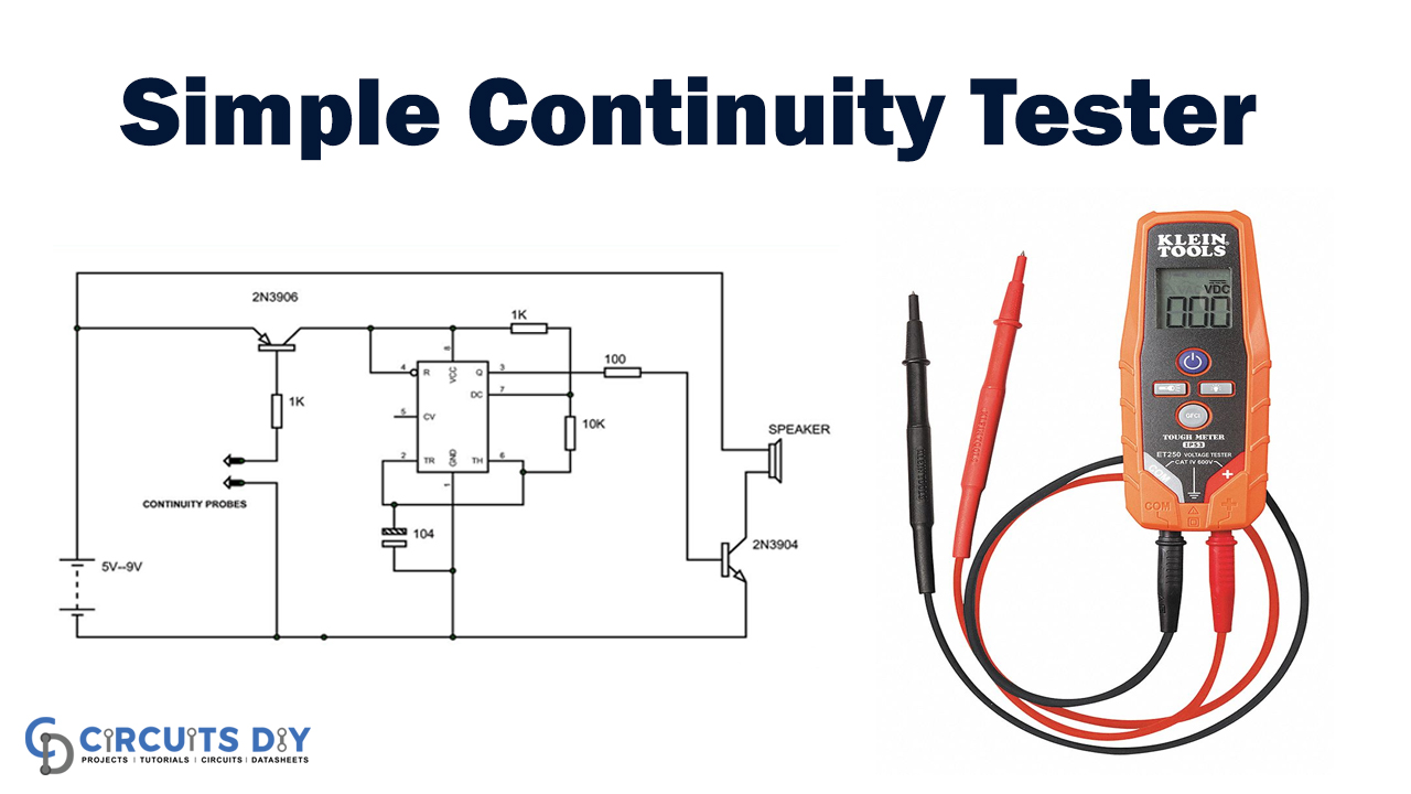
Simple Continuity Tester Circuit Diagram - Or in other words the device may be used for tracing faults or breaksin a particular conductor or a wire. In this circuit, we will build a very simple continuity tester, actually one of the simplest that can be built. By following the steps outlined in this article, you can easily build your own. It consists of a 9v battery,. You should also read this: Percy Jackson Cabin Test

Simple Circuit Diagram And Explanation - This circuit is developed from 555 ic timer circuit. It consists of a 9v battery, a 470 ω resistor, an led,. Learn how to make a continuity tester through a couple of simple circuit examples. Where do i connect the battery positive terminal? In this circuit, we will build a very simple continuity tester, actually one of the simplest that. You should also read this: Ecology Science Olympiad Practice Test

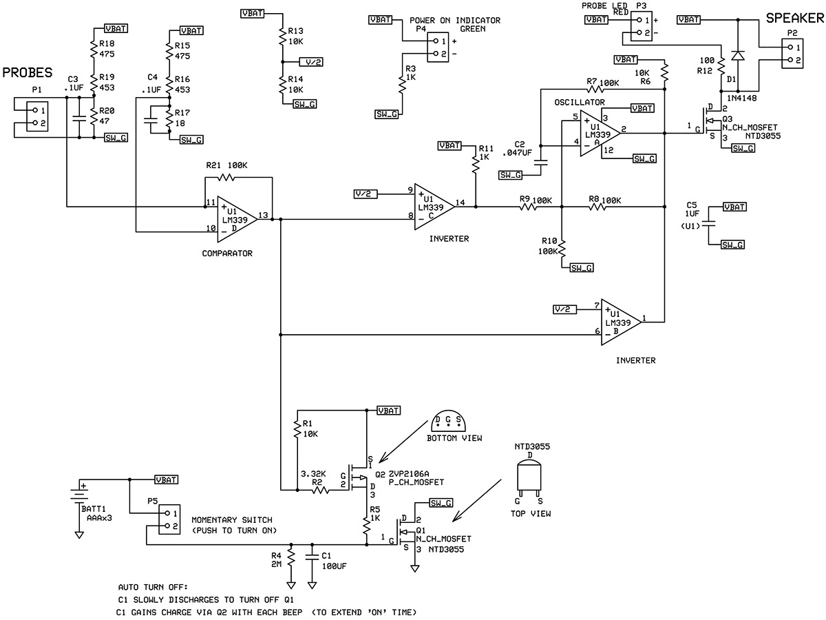
Simple Continuity Testing Circuit Diagram Using 555 T vrogue.co - A continuity tester circuit is used to check the flow of current in a circuit or component. Learn how to make a continuity tester through a couple of simple circuit examples. This simple continuity tester circuit constructed with single npn switching transistor sl100, this circuit will give visual and audio outputs when the continuity present at the probes. The circuit. You should also read this: Emissions Testing Trumbull Ct

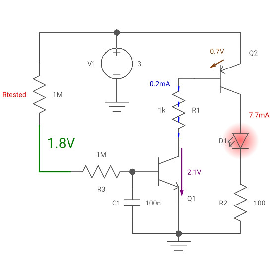
Simple Continuity Tester Circuit Diagram Circuit Diagram - A continuity tester circuit is a device that is used to detect the presence of continuity or break between the two ends of a conductor. It is a simple, cost. It consists of a 9v battery, a 470 ω resistor, an led,. A continuity tester is a device which is used for identifying the correct continuity of a particular conductor. You should also read this: Mold Testing Allentown Pa

Schematic Diagram Of Continuity Lamp Tester With Label Headcontrolsystem - Or in other words the device may be used for tracing faults or breaksin a particular conductor or a wire. This circuit is developed from 555 ic timer circuit. In this project we are going to design a simple circuit that can be used for continuity testing. It tests for various electrical faults in equipment and devices, ensuring continuity and. You should also read this: Does Hhc Show Up On A Urine Drug Test

Continuity Tester Circuit Diagram - The device is actually a simple led and a cell circuit, where the led is made to switch by passing the. The circuit may be used to trace out any break or interruption in complicated wirings and also remove short. This continuity test circuit can be used for testing. This simple continuity tester circuit constructed with single npn switching transistor. You should also read this: Cogat Test 1st Grade

Simple Continuity Testing Circuit Diagram Using 555 T vrogue.co - Simply put, it checks if the current flows freely from one end to the other. The simple continuity tester schematic diagram is a powerful tool for any technician. Learn how to make a continuity tester through a couple of simple circuit examples. A continuity tester circuit is a device that is used to detect the presence of continuity or break. You should also read this: Can You Get A Positive Pregnancy Test On Your Period

Continuity Tester Circuit Diagram Using Transistors Wiring View and - A continuity tester is a device which is used for identifying the correct continuity of a particular conductor in question. It is a simple, cost. In this project we are going to design a simple circuit that can be used for continuity testing. Here is a simple diy led continuity tester circuit which can be built in few minutes using. You should also read this: Genova Gi Map Test

Simple Continuity Tester Schematic Diagram Hen Using An Ohmm - The simple continuity tester schematic diagram is a powerful tool for any technician. A continuity tester is a device which is used for identifying the correct continuity of a particular conductor in question. As the name suggests, the continuity test checks the continuity of the current. A continuity tester circuit is used to check the flow of current in a. You should also read this: Sheinhire.com Product Tester

How To Perform a Continuity Test for Electric Components with Multimeter? - A continuity tester is a device that checks for continuity along a device to see if the. Learn how to make a continuity tester through a couple of simple circuit examples. The circuit may be used to trace out any break or interruption in complicated wirings and also remove short. Where do i connect the battery positive terminal? A continuity. You should also read this: Bridgeport Ct Emissions Testing